Today’s newsletter covers the three topics of planning with aerodynamic systems and statics 2.0.
You will find a good overview of each topic. We are of course at your disposal to answer your questions.
Planning of aerodynamic systems

In projects where aerodynamic systems are to be used, the planning process is a particular challenge. In addition to the sheer size of the project, which requires increased attention on its part, complex design criteria and various parameters must be calculated and taken into account.
Since aerodynamic systems often do not have a real roof connection, the testing and calculation of ballast must be carried out with the utmost care. In addition, there is always an interaction between interpretation and calculation.
At the latest with this type of project, the rough estimating is finally over!
As a result, the planning, which serves as the basis for offers, involves an enormous lyrity and time effort.
With the Solar.Pro.Tool, design and ballasting take place automatically and safely.
We take into account load reserves, wind loads and fault areas – you can be sure that your project can be realized exactly as you planned with the Solar.Pro.Tool.
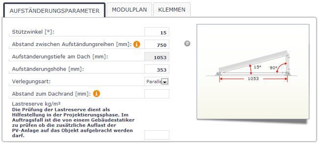
Depending on the system, different parameters can be changed for automatic design. The manufacturer may allow the support angle to be changed. The distance between the series is calculated automatically – but can also be changed retrospectively.
The system used in the example supports two types of design. “Parallel” – here the rows are aligned parallel to the Attica and “Diagonal” – here the rows are aligned vertically to the south.
Margin distances are defined with the system manufacturer – but you can also enter your own value.
By entering the load reserve, you have the option to store a value you know. We then take into account whether this value is exceeded within the interpretation.
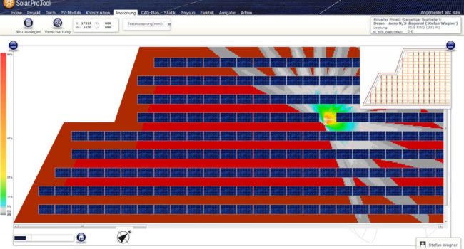
In the next step you will see the finished interpretation. You start the calculation of the shading manually – then you can remove modules in the places where no meaningful yield can be expected due to the shading.
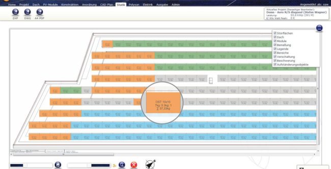
Here you can see an exemplary ballasting plan for a north-south design on a polygonal flat roof. The system used is ballasted with standard stones (7kG and 3kG). The required load and the stones to be brought in are shown in each module.
In addition, the individual modules are coded in color – yes, according to the boundary zone. This allows technicians and fitters alike to work with this plan in a simple, safe and efficient manner.
Depending on the system, additional values can be specified – As examples, the total load per unit or the maximum load per square meter can be displayed within the entire project.
Faster, safer and more efficient, you cannot plan aerodynamic systems!
Statics 2.0
We have taken the calculation of statics to a new level in cooperation with our structural engineer over the last few weeks.
In addition to a highly precise and safe design in the area of sloping roof and flat roof, the result is the transparency and traceability with which the calculation is carried out.
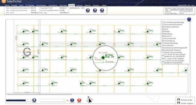
The precision and transparency can be seen, among other things, in the selection of the module rail (sloping roofs). At this time we assume a basic assumption – in area H we place three support on which we lay out the selected modules. On this basis, we calculate the real forces that work in the various aspects. When you change the rail, the data in the graphic is automatically updated.
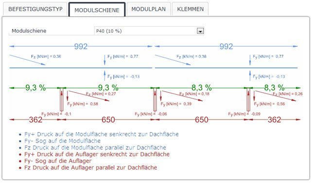
Where the calculations for rail selection are based on a basic assumption, the “Statics” section provides detailed information on the forces acting within the designed assembly system.
In the example shown, you will see a single-layer system. In addition to the maximum utilization of the fixed machines, you can also see the maximum utilization of the rails between the respective arresters.
This plan is can be enlarged. The figure also shows the activated magnifying glass function, which can be adjusted to various magnification factors.
Of course, this plan can be exported as DXF, DWG and PDF. The points in the legend then appear as separate layers in the CAD formats.


